Sunday, April 26, 2015

Vintage radio Sonos hack


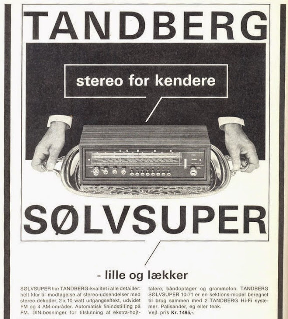
Introducing the Tandberg Sølvsuper 10 radio, a product of the Scandinavian Hi-Fi golden age. Sadly, after decades in storage, the huge variable capacitor inside has seized from corrosion and the radio was beyond repair.

So, what to do? Can this piece of 60s design be refurbished and made useful in the world of Internet of Things?

TANDBERG Sølvsuper 10, stereo for kendere


Lighting

To not mess up the original look too much I choose to keep the original front panel light bulbs, but two problems had to be tackled:

  1. The high voltage vacuum tubes had to be replaced with a modern LED array.
  2. LEDs to indicate which button was last pressed had to be fitted.

LED bar graph replaces same color radio tube

To connect a total of 22 LEDs I ended up using three 74HC595N 8-bit shift registers. The incandescent light bulbs were connected using transistors that could handle somewhat larger currents.


Rotary Encoders

I decided to keep the original logarithmic volume pots and make crude readings using AD converters. Because the pots are logarithmic, the accuracy at the lower volume levels is limited when reading using a linear ADC. I managed to get reliable readings of the values 0-10 using the Arduino built-in 10 bit ADCs.

For the tuning, bass and treble dials I wanted to use rotary encoders. I removed the mechanical wire drive connecting the tuning dial, variable capacitor and frequency display needle and connected the dial directly to a rotary encoder using a piece of wood. For the bass and treble dials I made plastic adapters that allowed the rotary encoders to fit against the back of the original pots. Then I broke of the potentiometer wipers to allow free rotation.
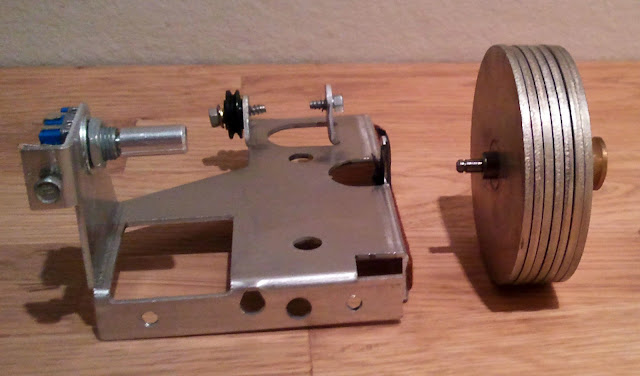


Original tuner dial weight and shaft removed

Stepper Motor

To drive the frequency display needle I'm using a NMB-MAT PG35L048 stepper with gearbox, that I found on eBay. I secured the stepper to the circuit board using a white metal bar from some old IKEA drapes. The original wheel fit on the stepper shaft using a piece of cardboard as a spacer.


Snortrekk diagram from the TANDBERG Sølvsuper 10 service manual


Mainboard

To make sure that there is no lag when operating the front panel dials and buttons, most user input is detected using interrupts and the stepper and speaker is driven using timers. I choose to use two Arduinos because of the number of interrupts required and because I need quite a lot of real estate given my limited soldering skills. Here's how the hardware was connected:

  • Front panel buttons connect to Arduino Mega using interrupts PCINT17-23.
  • Tuning dial rotary encoder connects to Arduino Mega, using interrupts INT5 and PCINT16. Rotary encoder push button connects to D13 using interrupt PCINT17.
  • IR and RF receiver connects to Arduino Mega using interrupts INT4 and INT2.
  • Ethernet board connects to Arduino Mega.
  • Bass and treble dial rotary encoders connect to Arduino Uno using interrupts INT0, INT1, PCINT10 and PCINT20.
  • Stepper connects to Arduino Uno using Timer 2 for stepping.
  • Speaker connects to Arduino Uno using Timer 2 for tone generation.
  • LEDs and light bulbs connect to Arduino Uno and are dimmable using PWM.

Sensor and RTC clock headers and 434MHz RF receiver daughter board


Ethernet and USB

The intertubes would not be possible were it not for the RJ45 jack. In addition to an Ethernet connector I added a back panel USB socket and a reset button for convenience.


USB, Ethernet and recessed reset button in original back panel
Read More...

Saturday, January 17, 2015

SonosUPnP library for Arduino

The UPnP protocol was invented by Microsoft and saw the light of day in the late 1990s. The purpose of UPnP is to allow devices on a network to automatically discover and interface with each other. Microsoft chose to base UPnP on the hottest standards at that time, namely XML and SOAP (both introduced in 1998). XML and SOAP have since been criticized for their verbosity and complexity.

Project goals:
  • Making it possible to both control and read the state of my home speaker system using UPnP.
  • Keeping the binary size and RAM usage low enough for the library to run on Arduino boards using the ATmega328 chip.
  • Learning more about writing parsers, using PROGMEM and the UPnP protocol.

Reverse engineering with Wireshark:

It isn't feasible to implement the entire UPnP protocol on a device like the Arduino, and reading protocol specifications can be tedious. Therefore, for small projects like Sonos speaker integration, it's sometimes faster to use a tool like Wireshark to get an understanding of and replicate some of the messages being sent over the wire.

To get started with Wireshark: download, install, select capture interface and click start. Tip: Use the filter function.

Using PROGMEM (Flash) instead of RAM for storing strings:

The Arduino Uno and Duemilanove boards use the ATmega328 chip with only 2048 bytes of SRAM. Normally when you use strings (char arrays) in your code, all the strings will get copied to the heap on startup and waste your precious RAM.

The SonosUPnP library contains almost 4KB of string data and it would not be possible to run on the ATmega328 without using PROGMEM for strings. More information about using PROGMEM:

Sending UPnP messages seems simple enough, but what about receiving and parsing?

One of my goals when writing the SonosUPnP library was to support reading state in addition to controlling the Sonos speakers. This capability is also what sets my library apart from the other Sonos Arduino libraries I've seen so far.

Again the challenge is the limited amount of RAM: How do you parse and read the values you are interested in from an XML file while only using a few bytes of RAM? To accomplish this I decided to write a library for this particular purpose: MicroXPath

Downloads:

Read More...

Wednesday, December 31, 2014

MicroXPath library for Arduino

There are probably hundreds of C++ XML parsers out there, but reinventing the wheel is fun. MicroXPath is a state machine which purpose is to enable XML navigation on the Arduino platform while keeping the memory footprint as small as possible. With only 2048 bytes of SRAM on the Arduino Uno conserving memory is quite important. The PROGMEM version of MicroXPath uses no more than 9 bytes of RAM. The length of the search strings is irrelevant, but two bytes are consumed (to store a PROGMEM pointer) for each XPath level when calling setPath. This means that no more than 15 bytes of RAM is used when searching for an XPath that is three levels deep.

Why XML?

Sadly XML is widely used for data exchange on the internet and it’s likely that you, at some point, will find yourself creating a project where reading data from an XML data source is useful. For me it was a project that I’m currently working on, where I need to read the status of my Sonos speakers, that triggered the need. The Sonos speaker system uses UPnP which in turn uses SOAP over HTTP.

Usage:

The library needs no configuration. There is one preprocessor directive called XML_PICO_MODE which is on by default and disables XML validation and error tracking.

When using the library, start by setting the XML search path by calling the “setPath” function. Don’t forget to specify the path depth (length of the search path string array). If the path is “menu”, “food”, “name”, the pathSize should be set to 3. When you have configured the path you can start passing characters to the parser using the “findValue” function. “findValue” returns true when the specified path is matched and the parser reaches the element end tag character. This means that the next character is the first character of the XML element content.

If you would simply like to get the text content of the XML element matching the specified XML path you can use the “getValue” function. The “getValue” function works in the same way that “findValue” does, but it takes a pointer to an output buffer and an output buffer size in addition to the character being parsed. It will return true when it reaches the end tag of the matched XML element. Text content will be written to the output buffer as long as there is room.

When searching for several paths within one XML stream you must search for them in the same order that they occur in the XML and you must change the path by calling “setPath” as soon as you are done reading content. Given the following XML:

<menu>
  <food>
    <english>
      <name>Toast</name>
    </ english >
    <price>$5.95</price>
  </food>
</menu>

If you are getting both the name “Toast” and the price “$5.95” from the XML stream, your code should look something like this:

char result[10] = “”;
// Set path of the first element
xPath.setPath((const char *[]){ " menu", "food", "english", "name" }, 4);
// Read until the matching element end tag is found or end of stream
while (client.available() && !xPath.getValue(client.read(), result, sizeof(result)));
Serial.print("Name: ");
Serial.println(result);
// Set path of the second element
xPath.setPath((const char *[]){ "menu", "food", "price" }, 3);
// Read until the matching element end tag is found or end of stream
while (client.available() && !xPath.getValue(client.read(), result, sizeof(result)));
Serial.print("Price: ");
Serial.println(result);

How does it work?

The parser is a state machine which cycles to a set of predefined states while reading the XML file character by character. For example: When at the root level and a < (less than) character is read, the state changes from XML_PARSER_ROOT to XML_PARSER_START_TAG. In addition to the parser state, to be able to match on a specific XML path, the parser needs to keep track of the current node level in the XML node tree, the match node level, the element name character position and the element name match position. This is all the state that is needed: 5 bytes + the single character being read.

Limitations:
  • The library does currently not support finding or reading XML attributes. I did not need this for my Sonos project so I decided not to spend time on it. The feature can be easily added. If you need it or would like to contribute: please contact me by emailing me (use the email address included in license of all source and example files).
  • Because the parser can only parse the XML stream once, top-down, you must know the order of the elements on beforehand when searching for multiple paths within the same stream.

Downloads:

Tool used to calculate RAM usage:
Read More...

Monday, July 4, 2011

Android App for the X10 project

I wrote this Android app back in 2011 and I'm publishing it now hoping that it might be useful. The app works together with the Arduino X10 libraries and communicates with the Arduino using REST + JSON.

This was my first attempt at writing an Android app and is most likely full of bugs. I used it to control my lights at home for a few years and the app did crash from time to time when the connection was bad (mostly crashed on 3G).

Downloads:

Similar projects:

In one of the comments on my "X10 with Arduino" post, Philip links to his own Android X10 home automation project. Please check it out on: androidmodbus.com
Read More...

Sunday, October 24, 2010

Arduino + Ethernet + RESTful JSON


Why use REST and JSON?

REST and JSON have become very popular the last few years and is currently supported by most platforms/development-frameworks (iPhone, Android, Java, .Net). REST with JSON is lightweight compared to protocols like SOAP, and in my opinion, much easier to understand. It is also quite easy to implement a RESTful web service on the Arduino.

Getting started:

Before you start implementing a REST web service in your app, it's a good idea to get familiar with it using a tool like the Poster add-on for Firefox. This add-in lets you interact with the service and use HTTP methods like POST and DELETE. Another great Firefox add-on is JSONView, that lets you view JSON response in the browser similar to how XML documents are shown.

The Arduino X10 RESTful JSON protocol:

I've chosen to use JSON only, XML is not supported. If you go to the base URI of the web service (http://arduino_ip/), you'll get a response containing the info and state of modules seen by the Arduino. "Seen" means all modules that have received messages on their address over the power line. Additionally the protocol supports storing module types (0 = Unknown, 1 = Appliance, 2 = Dimmer and 3 = Sensor) and user defined module names of up to 16 characters. State data, module types and module names are stored in Arduino EEPROM and survives power loss and resets. Here's an example of what the response looks like when I issue a GET request to the base URI on my setup:

{
  "module":
  [
    {
      "house": "A",
      "unit": 1,
      "url": "/A/1/",
      "type": 1,
      "name": "Amplifier",
      "on": true
    },
    {
      "house": "A",
      "unit": 2,
      "url": "/A/2/",
      "type": 2,
      "name": "Dining Table",
      "on": true,
      "brightness": 40
    },
    {
      "house": "A",
      "unit": 4,
      "url": "/A/4/",
      "type": 2,
      "name": "TV Backlight",
      "on": true,
      "brightness": 26
    },
    {
      "house": "A",
      "unit": 8,
      "url": "/A/8/",
      "type": 2,
      "name": "Hall",
      "on": false,
      "brightness": 69
    },
    {
      "house": "A",
      "unit": 9,
      "url": "/A/9/",
      "type": 2,
      "name": "Kitchen",
      "on": false,
      "brightness": 100
    }
  ]
}

If you are using several house codes you can get the JSON response for one specific house by adding the house code to the base URI like this: http://arduino_ip/A/. All my X10 modules use house code A, so in my case the response would be the same.
To get response for one module only you add both house code and unit code to the base URI as follows: http://arduino_ip/A/2/. The output would look like this:

{
  "house": "A",
  "unit": 2,
  "url": "/A/2/",
  "type": 2,
  "name": "Dining Table",
  "on": false,
  "brightness": 40
}

Updating fields with HTTP POST:

All fields except house, unit and url can be updated using post. If you are posting to the base URI of the service you need to include the house and unit code fields in the post data, if you are posting to a base + house URI you only need to include the unit code and when posting to a base + house + unit URI you only need to include the fields you would like to update.

Example 1 (turn of unit 2 on house A):

URI: http://arduino_ip/
METHOD: POST
BODY: house="A"&unit=2&on=false
RESPONSE: Info for all "seen" modules

Note:
When specifying house and unit in POST data the URI is ignored for update, but you still get the response for that URI. You could, for example, update state of module B3 by posting: house="B"&unit=3&on=true to URI: http://arduino_ip/A/1/, but the response will contain data for module A1.

Example 2 (set brightness of unit A4 to 90%):

URI: http://arduino_ip/A/4/
METHOD: POST
BODY: brightness=90
RESPONSE:
{
  "house": "A",
  "unit": 4,
  "url": "/A/4/",
  "type": 2,
  "name": "TV Backlight",
  "on": true,
  "brightness": 90
}

Note:
All POST data fields that result in something being sent over the power line (on, brightness and cmd) are exclusive. As soon as the parser finds one of these fields it will execute the command and stop the parser. Therefore: on, brightness and cmd commands should be the last field in the POST body.

Example 3 (changing type and name of unit A1):

URI: http://arduino_ip/A/1/
METHOD: POST
BODY: type=3&name="Light Sensor 1"
RESPONSE:
{
  "house": "A",
  "unit": 1,
  "url": "/A/1/",
  "type": 3,
  "name": "Light Sensor 1",
  "on": true
}

Deleting module state and info with HTTP DELETE:

Since there is no way for the Arduino to know if a module no longer exists in your setup, the web service lets you delete module data by issuing a HTTP DELETE request.

Example 1 (delete info for module A2):

URI: http://arduino_ip/A/2/
METHOD: DELETE
RESPONSE:
{
  "house": "A",
  "unit": 2,
  "url": "/A/2/"
}

Note:
The response will not be empty when you send the request to specific module URI. But when requesting all modules or all modules on one house code a deleted module will no longer be visible.

Example 2 (delete info for all modules on house A):

URI: http://arduino_ip/A/
METHOD: DELETE
RESPONSE:
{
  "module":
  [

  ]
}

Example 3 (delete info for ALL modules):

URI: http://arduino_ip/
METHOD: DELETE
RESPONSE:
{
  "module":
  [

  ]
}

Warning:
State data, types and names of ALL modules will be deleted permanently.

Using special HTTP POST field "cmd":

A complete RESTful representation of the X10 Extended protocol would be difficult to implement on the Arduino, and the binary size would grow out of proportions. Therefore I have implemented a simple way of using the X10 with Arduino Serial Protocol to send complex messages.

When using the "cmd" field it's possible to send multiple commands at once, simply by concatenating all the messages. This is useful if you want to implement scenarios in your application. The total length of the field value cannot exceed 60 characters (20 standard messages or 6 extended messages), anything longer than this will be ignored. Also keep in mind that the default command buffer size, defined in X10ex.h, is 16. This means that the buffer will run out of space after the 16th command.

Click here for more info on the X10 with Arduino Serial Protocol.

Example 1 (Turn off module A2 and A4):

URI: http://arduino_ip/ (URI is not important)
METHOD: POST
BODY: cmd="A13A33"
RESPONSE: Depends on the URI

Note:
REST service will not wait for command execution to finish when using "cmd" field. Because of this, the response you get back will not represent the state of the modules after the command has been executed. You can get updated state by sending one or more HTTP GET requests.

Example 2 (Turn on module A4 and set brightness of A2):

URI: http://arduino_ip/ (URI is not important)
METHOD: POST
BODY: cmd="A32A17x31x1E"
RESPONSE: Depends on the URI

Example 3 (Turn on modules 3 to 16 in house A):

URI: http://arduino_ip/ (URI is not important)
METHOD: POST
BODY: cmd="A22A32A42A52A62A72A82A92AA2AB2AC2AD2AE2AF2"
RESPONSE: Depends on the URI
Read More...

Saturday, October 16, 2010

X10 library performance optimization

When creating the X10 libraries I spent a lot of time on optimizing code performance and figuring out how to make all the code "non-blocking". The solution is a combination of using external interrupts, pin change interrupts and a timer overflow interrupt.

The ATmega168/328 chip has three timers, one of which is used to update the counters for the millis() and micros() functions. You can find a great article about the timers here:
http://www.arduino.cc/playground/Code/Timer1/
And one about pin change interrupts here:
http://www.arduino.cc/playground/Main/PcInt/.

What is blocking code, why avoid it?

The Arduino functions delay(), delayMicroseconds(), pulseIn() and pulseOut() all rely on some sort of loop that blocks other code from executing while their running. There is really no other simple way of implementing these functions. In general, any loop waiting for something to happen, f. ex. a pin going high, will block for as long as it's running. Another example of code that might block for some time is heavy calculations, like floating point math.

An interrupt can put any piece of code running in the main loop on hold, but an interrupt cannot disrupt another interrupt. Only one interrupt can execute at any given time. When the CPU finishes executing one interrupt it will trigger the next interrupt if the flag for this interrupt was set. If the code execution time of one interrupts is longer than the trigger interval of another interrupt, then the latter will only fire once when you might expect it to fire several times.

In code triggered by interrupts you should always avoid using blocking code. When using blocking code in an interrupt you not only stop execution of the main loop, but you might also prevent other interrupts from firing reliably. Even the timer overflow interrupt that updates the millis() and micros() counters is affected by this. If you rely on more than one interrupt to trigger consistently, like I do when sending or receiving power line messages at the same time as receiving RF and IR commands, you need to make sure that your interrupt triggered code runs as fast as possible. If you don't: expect execution/timing to become unreliable.

How to verify that code executes the way you planned:

A crude but quite effective way is using Serial.print(). You can even measure the performance of a piece of code using a combination of micros() and print(). There's an obvious problem though: using print() and other functions affect the performance of the code. The only way to really see what's happening on the inputs and outputs of the Arduino, is to use an oscilloscope.

I just borrowed an oscilloscope from a friend of mine and I'll show you the differences in performance between version 1.0, 1.1 and 1.2 of the X10ex library. One of the reasons the performance of the X10ex library is critical is described in the PLC interface manual. X10 messages are sent, one bit at the time, by applying a voltage to an input on the PLC interface in synchronization with a power line zero cross detection output. Basically: when the zero cross detect output goes high, you have about 50 microseconds to figure out whether to leave the input low or set it high by enabling an output pin on the Arduino. Another reason is to make sure it doesn't mess up the timings of the RF and IR libraries, since it uses interrupts to do most of the work.

The following images are screen shots of oscilloscope output. The first set of images show the delay from the zero cross detect pin on the PLC interface goes high until the output pin on the Arduino is set high by the X10ex library when transmitting.

v1.0. Zero Cross detect in red, Output in blue.
70us delay after Zero Cross detect reaches 2V.
v1.1. Zero Cross detect in red, Output in blue.
50 us delay after Zero Cross detect reaches 2V.
v1.2. Zero Cross detect in red, Output in blue.
10 us delay after Zero Cross detect reaches 2V.

The following are the same measurements done when flooding the Arduino with serial, RF and IR commands.

v1.0. Zero Cross detect in red, Output in blue.
Under stress the delay is up to 85 us after Zero Cross.
v1.1. Zero Cross detect in red, Output in blue.
Under stress the delay is up to 60 us after Zero Cross.
v1.2. Zero Cross detect in red, Output in blue.
Under stress the delay is no more than 25 us after Zero Cross.

The two last images are measurements done with the latest version of theX10ex library,showing signal length and three phase coupling at 50Hz.

v1.2. Output in blue. This image verifies that the output timer is
working correctly, disabling the output after exactly 1 millisecond.
v1.2. Output in blue. This image verifies that the output timer is working
correctly, repeating the 1ms output to align with zero cross of all phases.
Read More...

Tuesday, October 12, 2010

X10 with Arduino Serial Protocol


When creating a serial protocol for the Arduino X10 libraries, my goal was to create a protocol that was "human readable" yet lightweight and easy to parse/interface with. In my opinion, making a serial protocol human readable also makes it more understandable and hence easier to integrate with and debug. But there is a tradeoff: making it too literate makes it harder to parse.

Another goal was to use the same protocol when receiving and sending. By this I mean that whatever serial messages that originate from the power line, RF or IR libraries should look the same as the commands you send to the Arduino to control stuff. With the latest version of the protocol, it's possible to copy almost any message you receive and send it back to the Arduino to trigger the same command. This also makes the protocol easier to interface with, since you can use the same logic when reading and creating commands.

Here are some of the things I did to make it more human readable:
  • The first version of the serial protocol used ASCII values 0-255. A number of these ASCII values do not map to any displayable character or to characters like line-feed or tab. The obvious improvement here was to use two hex nibbles instead of one byte. Hex is easily parsable in C and is directly supported by the Arduino Serial libraries.
  • I've tried to use characters that would make sense to identify different groups of commands. The way the protocol is created all commands are sent in chunks of 3 characters, where the first character identifies the command type. Letters A-P are reserved for house codes, R = Request Module State, S = Scenario Execute and X or x means that the following two characters is a byte written in hex.

Here are some things I did that made it less human readable but easier to parse:
  • In the first version of the protocol the messages you received from the Arduino used a lot of words like "On", "Off", "PreSetDim", etc. Although this is easier to understand when you read it, it did not meet my goal of making it possible to use the same messages when receiving and sending commands to the Arduino. Although parsing commands like "A1_ExtendedCode_PreSetDim _50" is possible, it's definitely not easy to do in a few lines of code. So I decided to sacrifice some readability to get a smaller binary size. You can still enable debug mode to get the literate output though.

The Code:
  • Arduino X10 libraries – Libraries for power line, RF and IR communication and an Arduino test sketch implementing the X10 with Arduino Serial Protocol. 
  • X10.Net library – X10.Net serial communication library with test application. Written in C#.

The protocol:

The libraries and protocol support sending and receiving all standard and extended code X10 messages. Additionally I've added three custom commands: "Scenario Execute", "Request Module State" and "Wipe Module State".

Scenario Execute is a way of triggering sequences of commands and logic using a simple command. By sending message S01 you could, for example, set several X10 modules to different brightness levels and even make the events depend on some variable like the current time, ambient light or the state of another module. The scenario logic must be defined in the Arduino Sketch.

Request Module State let's you query the state of any appliance/dimmer module in your setup. Most X10 modules are one-way, which means that you can't query them for state directly. Because of that I added functionality to the X10ex library that enables it to monitor the power line and keep track of state automatically.
Another feature is the possibility to query state of all known modules on one or all house codes. This also serves the purpose of listing all modules used (that the Arduino has seen) in your setup. With standard X10 commands you would need to know the address of every module in use, or query every possible address, which would take about 4 minutes because of slow X10 power line signaling.
Request Module state has its own return prefix "MS:" and uses X10 extended code to return the on/off state and brightness level. Modules that haven't been "seen" by the Arduino (no state data stored) simply return nothing.

Wipe Module State makes it possible to wipe/clear module state stored in the Arduino EEPROM. State data is stored in EEPROM to make it survive resets and power loss. Currently you can either wipe module state of all modules by sending RW* message, or all modules on one house code by sending RWA (A = House Code A).

Return data Prefixes:

Prefixes are used when messages are sent from the Arduino to identify the message origin.

SD: Acknowledges a Serial Data message sent to the Arduino.
PL: Message originates from data received over the Power Line.
RF: Message originates from data received from RF remotes.
IR: Message originates from data received from Infrared remotes.
MS: Data originates from Memory State stored in Arduino EEPROM.

Error Handling:

"SD:_ExTimOut" Complete 3 or 9 character serial message was not received within one second from start to end.
"SD:_ExSyntax" Syntax error in serial message sent to the Arduino.
"PL:_ExBuffer" Power line message buffer full. Since X10 power line signaling is slow (about .3 to .6 seconds per message) the X10ex library needs to buffer incoming messages. The size of the buffer is defined in X10ex.h and defaults to 16 messages.

X10 Standard Messages examples:

A12 (House=A, Unit=2, Command=On)
AB3 (House=A, Unit=12, Command=Off)
A_5 (House=A, Unit=N/A, Command=Bright)
|||
||└- Command 0-F or _  Example: 2=On, 7=ExtCode, _ =No Cmd
|└-- Unit 0-F or _     Example: 0=Unit 1, F=Unit 16, _ =No Unit
└--- House code A-P    Example: A=House A, P=House P :)

X10 Extended Message examples:

A37x31x21 (A4, Cmd=ExtCode, ExtCmd=PRE_SET_DIM, ExtData=33)
B87x01x0D (B9, Cmd=ExtCode, ExtCmd=ShutterOpen, ExtData=13)
    |/ |/
    | └- Extended Data byte in hex      Example: 1F=50% bright.
    └---- Extended Command byte in hex  Example: 31=PreSetDim

Scenario Execute examples:

S03 (Execute scenario 3)
S14 (Execute scenario 20)
||/
|└-- Scenario byte in hex (Hex: 00-FF, Dec: 0-255)
└--- Scenario Execute Character

Request Module State examples:

R** (Request buffered state of all modules)
RG* (Request buffered state of modules using house code G)
RA2 (Request buffered state of module A3)
|||
||└- Unit 0-F or *        Example: 0=Unit 1, A=Unit 10, * =All
|└-- House code A-P or *  Example: A=House A, P=House P, * =All
└--- Request Module State Character

Wipe Module State examples:

RW* (Wipe state data for all modules)
RWB (Wipe state data for all modules using house code B)
|||
||└- House code A-P or *  Example: A=House A, P=House P, * =All
|└-- Wipe Module State Character
└--- Request Module State Character


X10 protocol external resources:
Read More...

Wednesday, June 30, 2010

X10 RF & IR remote using Arduino


Goals:
  • Create a platform independent solution that makes it easy to interface with X10 hardware and that supports sending and receiving both standard and extended X10 messages.
  • Make a cheap alternative to the Marmitek CM15PRO Computer Interface with better functionality, performance and RF-range.
  • Incorporate X10 IR into the solution to make products like the Marmitek IRRF7243 or the XanuraHome IRIX35 interfaces redundant.
  • Base it on the Arduino platform using a single Arduino Duemilanove controller.
Challenges:
  • Writing interrupt triggered non-blocking PLC1, RF and IR libraries that can be run in parallel on one ATmega168 chip without using too much resources or getting in the way of each other.
  • Making RF and IR performance good enough to be able to receive BRIGHT and DIM commands and forward them to the PLC1 interface without getting choppy dimming.
  • Using one of the ATmega168 pin change interrupts. Separate interrupts are needed for PLC1, RF and IR. The Arduino Duemilanove only has two external interrupts, but it's possible to use three additional pin change interrupts. Check out chapter 11 in the ATmega168 datasheet for more information.
Limitations:
  • RF library (X10rf) only tested with 434MHz KR22 remotes. Timing min and max values (defined in X10rf.h) may need changes to make library work with other remotes.
  • IR library (X10ir) only tested with Logitech Harmony remotes. Timings defined in X10ir.h can be changed to make it work with other remotes using the same protocol.
Future Enhancements:
  • Support for the WiShield 2.0 by AsyncLabs.
  • Android and iPhone apps.
  • Bluetooth Support.
Download the code:
  • X10ex library – X10 message transmission and reception using a PLC interface. 
  • X10rf library – X10 message reception using a standard 434 or 315MHz RF receiver.
  • X10ir library – X10 message reception using a standard, low cost IR receiver.
  • X10 test sketch – Example code using above libraries, including X10 serial protocol that works with the X10.Net library and code for the Ethernet shield.
  • X10.Net library – X10.Net serial communication library with test application. Written in C#.
The hardware you need:
  • Arduino Duemilanove board (ATmega328).
    Price: SparkFun ~$30, eBay ~$20
  • Marmitek XM10 Two-way PLC Interface2 or equivalent US version.
    Price: IntelliHome.be ~$50 (I live in Europe, X10 stuff is expensive)
  • 434MHz receiver module (I'm using one based on the Infineon TDA 5200 chip).
    Price: Similar product from SparkFun ~$5
  • IR Receiver (I'm using the Everlight IRM 3638N3).
    Price: Elfa.se ~$2, Similar product from SparkFun ~$2
Total Price: ~$77

The hardware it's replacing:
  • Marmitek CM15PRO Computer Interface.
    Price: ~$115
  • Marmitek IRRF7243 IR Mini Controller3 or XanuraHome IRIX35 Infrared Interface4.
    Price: ~$58 or ~$150 for the IRIX35
Total Price: ~$173 or ~$265

Harware used for testing:
  • X10 extended code capable two-way dimmers, appliance modules, etc.
  • Two Marmitek KR22 RF remotes (~$25 a piece).
  • Logitech Harmony 785 (using device Marmitek IR7243 to send X10 IR).
  • So far the library has been tested with the 50Hz European XM10 and the 60Hz North American PSCO5 PLC interfaces. Other models should work fine too. Thanks to the guy at http://brohogan.blogspot.com/ for testing the PSC05 :)
Credits:

I want to thank Jaime from Spain, for his contribution to getting me started with the Arduino Ethernet shield and for giving me useful information on the workings of the iPhone and Android platforms.

I also want to thank BroHogan for his excellent blog that inspired me to start my X10 project, and for his help on testing my libraries with North American PLC interfaces and 310MHz RF receivers.

If you want to know how to re-tune the 315Mhz RF receivers from Sparkfun to X10 compatible 310MHz receivers, check out BroHogans blog.

Resources:

1 PLC = Power Line Communication
2 The XM10 seems to have way better PLC signal strength compared to the CM15PRO.
3 In my opinion the IRRF7243 is not worth the money because of poor IR range and choppy dimming.
4 Never tested the IRIX35, but with a price of ~$150 I assume it’s a lot better than the IRRF7243.
Read More...